Audio Spectrum Analyzer: Planning

Awhile back when I was looking for simple electronics projects, I found this Easy LED Color Organ project.  It was easy enough to breadboard, but the results weren't very interesting   since it was just on or off for bass, treble, etc.

Then I found this Audio Spectrum Analyzer project, and that seemed more promising, though according to a friend the circuitry was not very well designed.  Instead he recommended using the circuitry to isolate the frequency bands used in this more complex version of the LED Color Organ. I combined that with the 10 LED displays from the spectrum analyzer, using the suggested LM3916 chip to drive the display as a simpler replacement for several resistors and other components.

The initial schematic looks something like this, with stereo input and output and some overall volume controls. There's probably still some changes that need to be made or bugs that need to be fixed, but I'll iron those out when I run into them.

Schematic

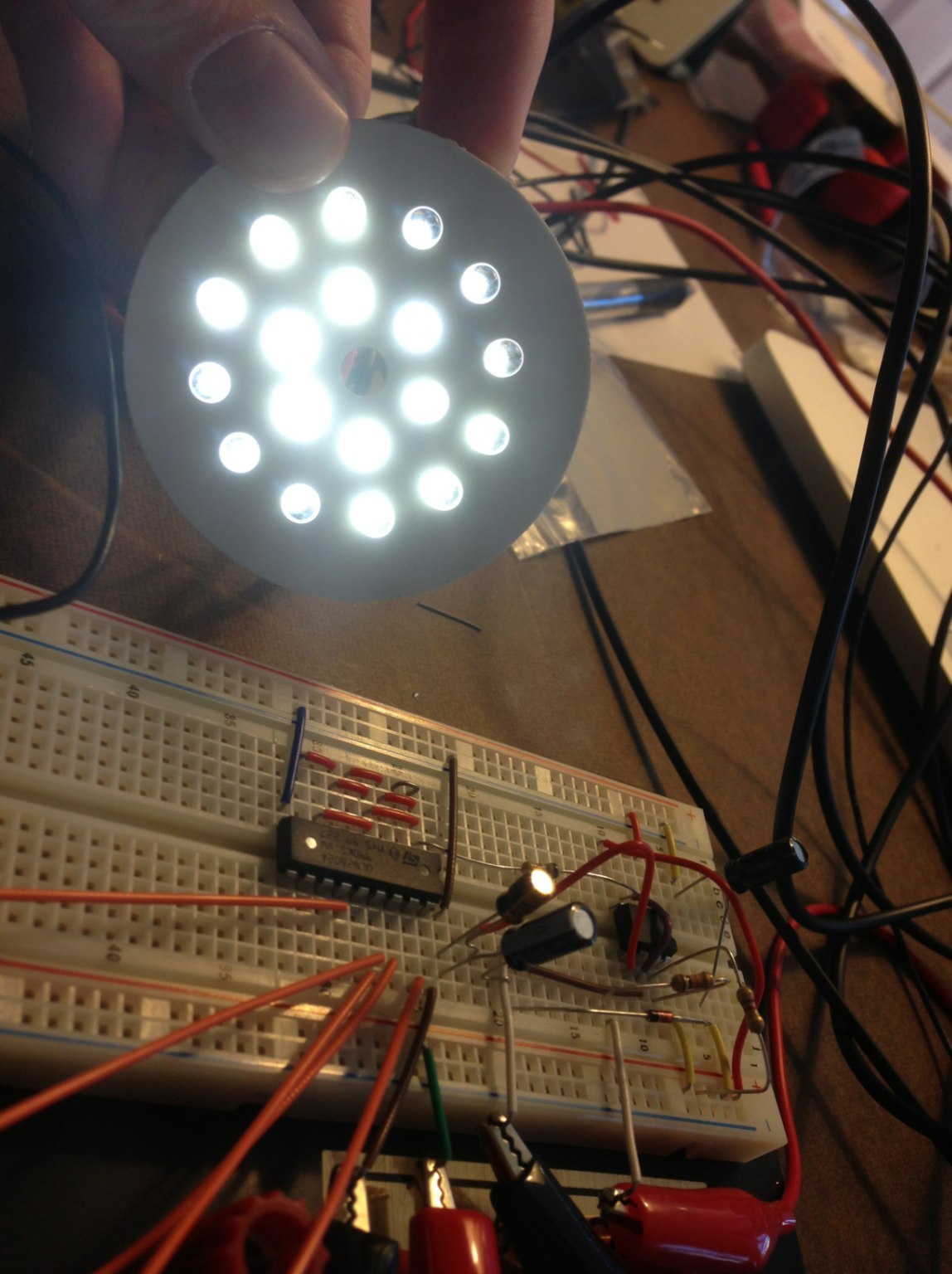
I breadboarded most of that circuit for a test and took a video.

Since that seemed to work out well enough, I started to plan how to put the final circuit on a circuit board. I got a 55x40 hole circuit board which is slightly longer than will fit in the 5.5"x4.5" box I have to put it in. I laid out the circuit to see how it would fit in that space. I wanted to add 8 frequency bands with 10 LEDs each to have more detail, and it seems like this configuration with some 80 LEDs is about the max that will work on that sized board or in that size container. 

Circuit Diagram

Well that's all for now, I order the rest of the parts and when they arrive I can start soldering.

Finishing and Staining the Solar-Powered Stereo

We finished the Solar Powered Stereo this week, I think it came out really well. 

image.jpg
image.jpg

Looks a lot more professional than I imagined when I first decided to start this project.

Continuing where I left off from the last update, after the glueing, we needed to a lot of cleanup:

image.jpg

After a little power sanding and rounding the corners with the router, it looked much better:

image.jpg

Next we had to make a rabbet in the storage compartment for the door to close against:

image.jpg
image.jpg

 Fitting the door, cut from the same plywood as the back and front panels:

image.jpg

 After the first coat of stain:

image.jpg

Applying a coat of wipe-on polyurethane: 

image.jpg

After four coats of poly, I put on the metal feet and leather handles I bought from a guitar amp parts website:

image.jpg

Went with black for the the color of the speaker grilles:

image.jpg
image.jpg

We built a housing to sit on top of the solar panel and plexiglass. Edges were cut diagonally and glued together. You can also see the LED power indicator I mentioned previously, through an LED lens:

image.jpg

 Since the housing was glued end grain to end grain, on a side with very little surface area, it wasn't going to be a very strong bond. So we cut slits in each corner, and glued in a spline of another piece of wood. Since we could, we went with a spare piece of mahogany which added a nice accent color:

image.jpg

The wires coming from the solar panel had gotten a bit frayed after removing the unit from the original plastic case it was glued into and were no longer providing a reliable connection, but it was pretty easy to desolder them and solder in new ones. Testing the new connections:

image.jpg

Solar panel housing and door screwed on for the first time. Hinges are recessed into the door to allow it to close tightly:

image.jpg

Staining and applying polyurethane to the door and housing. You can see the knob for the door here. It was glued to a dowel, which in turn was glued to a hole in the door:

image.jpg

Final assembly. You can see the charging indicator LED from the solar panel lit up from the sun:

image.jpg

Used a magnet catch for cabinet doors, it's a little strong for the size of the door, but it has some play so I could try and recess it more to limit the strength:

image.jpg

One interesting and fortunate development was that although the first time we test fit everything and tested how the speakers sounded, they didn't sound that great. At the time I figured it was because the space inside the box was too small for the power of the speakers to have a completely sealed box like we did. But then we ended up notching these corners around the right speaker hole to make it possible to insert and remove the battery through that hole:

image.jpg

This seems to have acted like a "port hole", allowing air to escape, but the notches still fit under the speaker grille to hide them and limit exposure to the elements. This, quite luckily, seems to have significantly improved the quality of the sound the stereo produces.

Building the Solar-Powered Stereo Box

A friend and I have been working on making a wooden case for the Solar-Powered Stereo in our spare time for a few weeks (stretching into months) now.  Since he's pretty knowledgeable about woodworking and has quite the selection of dedicated tools for the job, we've really gone all out in a couple of ways.

First, we could have just used nails or screws to join the separate pieces of wood together, but instead we used more complicated techniques like dovetail joints, mostly for aesthetic reasons. 

We also used select pine and planed the pieces of wood down to get the desired thickness and ensure the edges were at 90 degree angles from each other.

The sides are made out of 1/4" plywood, and we cut grooves for them to be inserted into so they didn't require any glue or screws. The pieces of pine used for the storage compartment are a little thicker to give room for this groove on the outside, and for rabetting for the door on the inside (though the rabetting has not been done yet in these pictures):

Inside the storage compartment, we cut a hole for the amplifier's controls to be accessible through, and also one for the cigarette lighter socket (for charging mp3 players, etc.), and one for the 1/4" stereo cable jack. The amplifier casing also had to be modified to fit better in the hole. We also used a biscuit joiner to make a stronger connection between the vertical and horizontal pieces of the storage compartment.

One major concern was that, since the battery is the majority of the weight, it needed to be firmly secured to the case to prevent it from moving around inside and bumping into other components.  This also would allow the stereo to be carried in any orientation.

To accomplish this, we bent a wire to the form of the battery, and attached it with screws to some wood blocks which were in turn glued to the inside of the case.  There's some extra room to allow the battery to be taken out and put back in, and some pieces of wood used as removable shims to make it secure.

You can also see in that picture that the speaker hole above where the battery sits has square corners cut into it.  This was because we decided to make the back panel not removable to simplify the design, but still needed a way to get the battery in and out.  The speaker hole was not quite big enough for the battery to fit in at the angle it needed to in order to go inside the case. but with the corners cut, it fit in nicely.  It's a little bit of an ordeal getting the battery in and out, but hopefully it's not something that will be done very often.

The next step was to put everything together for a test of the sound.  You can also see the recessed area in the top where the solar panel will go.

Everything worked fine, though I don't think this makes the best speaker box.  For the size/power of the speakers, I don't think there's enough volume inside the box for it to be sealed like it is, and it might sound a lot better with a port hole cut to allow air to flow out.  I don't really know much about speaker box design, but I do know that adding a hole would mean it would be really easy for dirt or sand to get in if I took it to the beach, and it would really reduce the water resistance.  

So there might be some conflicting goals here (small size and portability and resistance to water/the elements, versus the best sound possible), but I think this is probably the right set of compromises for the intended outdoor use of this device.

The next step was to glue everything together. It required a lot of clamps. 

Next, there's a lot of sanding and staining to do, plus adding a door for the storage compartment and a housing for the solar panel, and lots of other finishing work. 


Previous posts about the Solar-Powered Stereo project: 

Charging the Battery From a Wall Socket 

Speaker Crossover Filter

Power indicator LED, voltage gauge

Solar-Powered Stereo (test build)

Solar-Powered Stereo (casing and schematics)

Solar-Powered Stereo (part 1)


LED Desk Lamp

I saw this interesting Little Big Lamp project to make an LED desk lamp on Make, and it looked easy enough to make, so I gave it a shot.  It involved making a circuit with a 555 timer and darlington array to control the brightness of the LEDs, and a case made out of PVC piping and ABS plastic.  It went relatively smoothly, though I had a lot of help with tools and experience from a friend.

Here's some pictures of the building process: 

Here's some pictures of the final result:

One thing I didn't like about the original design was that the cord from the power supply was directly soldered into the circuit board of the lamp, and there was no power switch on the lamp.  While there might have been a dimmer, there was no easy way to shut the lamp off without unplugging it from the wall.  So I added both a power switch, and a barrel plug for the plug on the power supply so the cord could be removed and easily replaced.

IMG_0691.jpg

One issue I did have is that I tried to avoid buying the extension spring called for in the design for bending the PVC pipe smoothly after you heat it up with the heat gun, and we just tried to bend it around another cylindrical object.  This did not produce good results, as the circular shape of the pipe flattened. You can see how my first attempt didn't look great:

It almost looked alright, but I decided to try again with the spring to help the pipe not cave in on itself or fold, and the results were much better:

D90D0B43-9DD9-463C-94CF-8F0FC33A7778.jpg

As you can see though, the spring itself wasn't so lucky.  After the PVC re-hardened, it was quite difficult to remove the spring, and I had to use so much force pulling it out that it got bent.

Charging the Battery From a Wall Socket

I decided it might be handy to have a way to charge my solar-powered stereo quickly and in situations where direct sunlight was not available, so I looked into how to charge batteries by plugging them into a wall socket. 

Obviously the power needs to be stepped down from the 120 volts coming out of my wall sockets to the 12 volts the battery can handle, which requires a transformer of some kind. Even after transforming the current down to 12 volts, the amperage will be pretty high, which is what we want so it can charge quickly, but it also introduces the risk of overcharging the battery. This is a risk that isn't really a concern for the solar panel, because the amperage it puts out is so small in relation to the size of the battery that overcharging is not something to worry about.  

Basically what we need here is a battery maintainer (aka battery mender) to take care of those two problems. But there are a few special concerns for this application of that technology.  First, we need to make sure the battery maintainer we choose is compatible with sealed lead-acid batteries.  A typical car battery is lead-acid, but uses different technology than sealed lead-acid batteries. The battery I've chosen is the absorbed glass mat variety of sealed batteries, but there is also a "gel cell" type. Besides compatibility with this battery, we want something that will charge the battery from a drained state reasonably quickly, but will not overcharge the battery. The Deltran Battery Tender brand of battery maintainers seems to be reviewed well on amazon. There is a "Plus" model, but the Junior model seems to be a good choice for me just because it's smaller and cheaper, but still does everything I want.

That charger says it is compatible with "all 12-volt lead-acid, flooded or sealed maintenance free batteries (AGM and gel cell)", and that it has a "4-step charging program (Initialization, Bulk Charge, Float Mode)," so it can charge the battery up from a discharged state quickly, but will slow down when the battery is nearly full to ensure it doesn't overcharge it. Here's a graph of the voltage and amperage over time and a description of the 4-stages from Deltran:

Screen Shot 2013-08-06 at 11.24.30 PM.png
Step 1) Initialization: Red Light On or Red Light Flashing: Monitor Circuit verifies appropriate battery voltage levels and good electrical continuity between the battery and the charger DC output.

Step 2) Bulk Charge: Red Light On, Green Light Off: Constant Current at Full Power. Bulk Charge ends at approximately 75% to 80% of full battery recharge.

Step 3) Absorption Charge: Red Light On, Green Light Flashing: Constant Voltage at Absorption Level. This conditions the battery for optimum performance. Absorption charge ends when the battery charging current drops below the optimum recharge threshold or the absorption timer expires.

Step 4) Float Charge: Red Light Off, Green Light On. Constant Voltage at Float / Maintenance level. Keeps battery fully charged and maintains high specific gravity. Full charge reset monitor protects battery against excessive appliance current draw while charging. Float charge continues indefinitely
— Deltran Battery Tender Junior Product Description

One issue with the Battery Tender Jr is I want to be able to plug the stereo into the wall without taking it apart, so the charger would need to be able to plug into the cigarette lighter socket I put in the easily accessible storage compartment of my solar-powered stereo.  But the Battery Tender model chargers don't seem to come with that adapter.  It is on sale from Amazon separately, but it is currently $8 or so when you include shipping:

  Since this is also a Deltran Battery Tender brand product, it should work fine with the Junior model charger. I chose to use the same style cigarette adapter that came with the solar battery maintainer I bought, and the polarity was the opposite of the Battery Tender brand products, so I had to open up the part that plugs into the cigarette lighter and re-solder it to reverse the polarity. Here's a diagram from Deltran that illustrates the polarity of their connectors:

As you can also see from that diagram, the adapters that ship with the Battery Tender Jr come with 7.5 amp fuses embedded into them (to protect the battery charger itself in the case you were to short it out, it's pretty unlikely the fuse would trip in the case it was connected to a battery and charging normally).  The cigarette lighter adapter I used shipped with the solar panel, so it came with a much smaller 0.5 amp fuse, but it can be replaced with one of the correct amerage. I used this 5x20mm 250v 7a fuse from RadioShack. I'm not sure if that Deltran Battery Tender brand cigarette lighter adapter is fused or not, it doesn't say on the Amazon page or on Deltran's website.

Here's the Battery Tender charging the battery directly via the clip connectors, and via the cigarette light adapter:

One last important consideration is that the Battery Tender only be connected when the battery is also connected. The Battery Tender is definitely capable of putting out a higher voltage than 12 volts, and could easily damage the components in the amplifier if they are not rated for higher voltages, which they are likely not since it is a low-cost amplifier. Not turning on the amplifier while the Battery Tender is connected (strongly recommended) protects the components after the power switch, but there are capacitors before the power switch that could be damage if charging is attempted without the battery connected. Connecting the battery will lower the overall amount of voltage running through the circuit, and thus protect the other components. Presumably the battery would always be connected, but if somehow the fuse between the battery and the rest of the circuitry was blown, then it might appear connected when it is not.  So before plugging the battery tender in, it's worth turning on the amplifier to confirm the battery is connected, then turn it back off again before charging.

Previous posts about the Solar-Powered Stereo project: 

Speaker Crossover Filter

Power indicator LED, voltage gauge

Solar-Powered Stereo (test build)

Solar-Powered Stereo (casing and schematics)

Solar-Powered Stereo (part 1)

Speaker Crossover Filter

The Problem

If you were to carefully read the product specifications for the Class-T Audio Mini Amplifier and Marine Certified Speakers I'm using in my solar-powered stereo, you would notice that the Amplifier produces frequencies ranging from 20 hertz to 20 kilohertz (about the range of human hearing), but the speakers only can reproduce 60 Hz to 20 kHz. Feeding the speakers lower frequencies than they can handle is not ideal (and actually potentially damaging to the speaker), but there is a solution: a crossover filter.


What is a Crossover Filter?

DIY Audio & Video has a good Speaker Crossover Wiring FAQ that has this explanation of a crossover:

What is a crossover?

People can hear sound frequencies from 20-20000Hz. There is no one speaker capable of producing all frequencies throughout this range. Therefore, multiple speakers must be used. Usually, it is damaging for a speaker to produce frequencies lower than what it was designed for. Also, if two speakers produce sound at the same frequencies, then the sound at those frequencies will be louder. For these reasons, some type of circuit is necessary to make sure that each speaker only produces a certain set of frequencies. That circuit is a crossover.
— DIY Audio & Video: Speaker Crossover Wiring FAQ

This image from their site illustrates the point: 

crossover.gif

Fortunately for my stereo project, the woofer and tweeter are part of the same package, so they have already been corrected for the overlap frequencies.  But I still have the problem of the amp producing frequencies too low for the speakers to reproduce. This will lead to the speakers sounding distorted at moderate to loud volumes when reproducing lower frequencies. This same crossover filter can be used to remove all frequencies too low for the speaker to reproduce correctly.


What do I need to make a Crossover Filter?

What makes a crossover?

The basic components of crossovers are inductors and capacitors. Inductors become more reactive (increasing AC resistance) as the frequency increases, and thus lower the sound pressure on the driver more and more as the frequency increase. Capacitors work just the opposite. They have higher AC resistance as the frequency decreases. Inductors, Capacitors, and Resistors are also used in other circuits like Notch Filters and Attenuation Circuits which can sometimes be included in the ‘crossover’.
— DIY Audio & Video: Speaker Crossover Wiring FAQ

For my purposes, the simplest type of crossover will do. That type is the 1st order Butterworth crossover.  Here's an illustration (from DIY A&V):

HighFrequencyCrossover.gif

As you can see, they placed a capacitor on the positive lead to the tweeter to filter out frequencies below 3000 Hz @ 8 Ohms (random values for this example), because capacitors have higher AC resistance as the frequency decreases, so this will filter out low frequency sounds that could be damaging for the tweeter. Conversely, they put an inductor on the woofer to eliminate higher frequency sounds. Here we are only interested in removing lower frequencies from our speaker, so we will only use a capacitor, and we will place it before the entire speaker system.

What type of capacitor should I buy?

For capacitors, a polar Electrolytic capacitor is your basic type. They are cheap, but do not pass high frequencies well. Mylar capacitors are more expensive, but they are better for audio because they work better at the high frequencies, and have less inductance and resistance. Metalized Polypropylene capacitors are the best, but are also much more expensive. Again, be sure to investigate the resistance of these components before purchasing.
— DIY Audio & Video: Speaker Crossover Wiring FAQ

For my purposes, I just bought Aluminum Electrolytic Capacitors, but I opted for the Non-polar/Bi-polar variety because they are better for audio purposes.

The next question is, what value capacitor should I buy? A crossover filter has 3 variables:

  • the impedance of the speaker (Ohms)
  • the frequency (hertz) below which you want to filter, and
  • the capacitance of the resistor.

We know from the specifications that our speakers are 4 Ohms, and we want to filter at 60 Hz because the speaker's rated Frequency Response is 60 Hz to 20 kHz. With these two variables, we can calculate the 3rd. DIY A&V has a Crossover Calculator for this purpose. The results for my specifications are as follows:

Screen Shot 2013-08-02 at 10.36.18 AM.png

Again, ignore the inductor portion, we are only concerned with the value for the capacitor, which is calculated to be 662.5 microfarad. From here I went to Mouser to search for this value capacitor. Now maybe you can guess this, but 662.5 uF is not a standard value for capacitors that are normally manufactured.  So I needed to look for something close to that value.

I could either round up or round down, and if you do the math (or use the calculator to check), you'll see that lower capacitance means the cutoff frequency increases, so I would start losing frequencies above 60 Hz that my speaker is perfectly capable of reproducing. Conversely, if the capacitance value increases, the cutoff frequency decreases, and if you go to far down in capacitance we're no longer solving the problem of removing frequencies the speaker cannot accurately reproduce. So you have to be careful going in either direction. Also, be aware that manufacturing tolerances on the speaker, amp, capacitors, etc are not very tight, so it's not possible to be too accurate until you actually buy the parts and measure the values yourself.  But I'll discuss manufacturing tolerances more later.

The closest value for a widely manufactured capacitor I could find was 680 uF. Though unfortunately there did not seem to be any non-polar/bi-polar capacitors at that capacitance. 


Wiring in Parallel or in Series

I can’t find a inductor/capacitor/resistor of the value I need. What should I do?

When you buy inductors capacitors or resistors there are usually only certain values available. ... If you cannot find the component you need, then go with the closest match. You can also combine two components in Parallel or Series to get a different value that you can’t find normally.
— DIY Audio & Video: Speaker Crossover Wiring FAQ

The Basic Electronics page at DIY A&V  explains how you can wire capacitors in parallel or series to obtain a higher or lower value for overall capacitance. Here's a few illustrations from that website:

capacitorSeries.png
capacitorParallel.png

On the left is the diagram and formula for wiring in series, and on the right is the same for wiring in parallel. If you do the math, you'll find that the overall capacitance is reduced if you wire multiple capacitors in series, and increased if you wire multiple capacitors in parallel. With our target value of about 660 uF as a starting point, capacitors generally get more expensive as the capacitance increases, and cheaper (and more common) as the capacitance decreases (at least until you get to very low values, then price and rarity might go up again). So for our purposes, we want to wire in parallel to be able to use more commonly found resistors. 660 uF is not a very common capacitance value, but 330 uF is, so I used two 330 uF capacitors wired in parallel for a total capacitance of 660 uF. The particular capacitors I bought are from mouser at this link:

Nichicon Aluminum Electrolytic Capacitors - Leaded 50volts 330uF 85c 16x31.5 7.5LS

I ordered capacitors with 50 volt rating because you want to have a lot of headroom over the actual power that will be going through the circuit so the capacitors don't blow out. 50 is a good minimum, it's fine to go higher, but the capacitors will increase in physical size (they are already pretty big at 50).


Manufacturing Tolerances

Here's where things get interesting.

If you look at the specifications for the capacitors I linked to above, you'll see that they have a tolerance rating of 20%. This means that even though it's listed as a 330 uF capacitor, what you actually get might have a capacitance of +/- 20% of that value, so from 264 - 396 uF. As you can imagine, this has a pretty large impact on our calculations.

It's not just capacitors that have wide tolerances, the speakers, amplifier, resistors, all of them are manufactured to specs to some degree of accuracy. If you pay a lot of money, you can buy components with very narrow tolerances. But the cheaper option for manufacturers is to have wide tolerances, and rate their products accordingly. For good manufacturers, this usually means they will err on the side of giving you a better product than the rating.

So I ordered 10 of these capacitors (I only need 4, but bulk pricing kicks in at 10 for Mouser, and it's helpful to have spares), and then measured them when they arrived with a multimeter that can measure capacitance. Then I did some calculations to figure out what the actual cutoff frequencies would be (I used this other crossover calculator this time, because it lets you plug in capacitor values and get the responding corner/cutoff frequency, and not just the other way around). Here are the results:


The first thing to notice here is that the measured capacitance of the capacitors is about 8-12% greater than the rated values. Capacitor manufacturers usually err on the side of increased capacitance, because more capacitance is not a problem in the most common circuits.

Calculating out the cutoff frequencies results in 53.7 Hz to 55.7 Hz for 4 Ohm speakers, which is what the speakers I bought are rated. But, if you were to measure the resistance of these speakers, it is actually 4.4 Ohms, so that means the cutoff frequencies will be closer to the range of 48.8 Hz to 50.6 Hz. This is a little lower than the 60 Hz minimum frequency response the speakers are rated for, but hopefully the actual response of the speaker is a little better than the rating. And filtering out the really low frequencies is the most important thing anyway, as they are the most distorting or potentially damaging.

So now I just had to wire these capacitors in parallel. Being an amateur myself at soldering and circuitry, this is what I came up with at first: 


IMG_0659.jpg

My roommate (who is much better with electronics because he makes and sells his own guitar pedals)  saw this and suggested a much simpler design by wrapping the two capacitor's leads together and soldering them to a wire as if they were one:

After installing these, the speakers distort a lot less when compared to the same volume & EQ setting being played through a simple speaker wire with no crossover filter. 

Now the focus will shift to building the casing.  One small aspect of that will be securing these capacitors to something (whether it be through glue or zip-ties, etc) so they don't move around and potentially short something out with their exposed metal.  


Previous posts about the Solar-Powered Stereo project: 

Power indicator LED, voltage gauge

Solar-Powered Stereo (test build)

Solar-Powered Stereo (casing and schematics)

Solar-Powered Stereo (part 1)